Published On Nov 30, 2010
heres an example i tried to draw of the pulser circuit
http://magneticitist.webs.com/cap%20p...
as i said i have no idea if someone else came up with this already.. but i have searched far and wide looking for various solid state timing circuits that can drive a relay and all i come across are 555 and other IC circuits.. these are all too complicated for me, or rather i dont get them enough to feel confident. all i want is a timer that drives a relay and i have no idea how much those 555 circuits require for input. (5 or 12v?) i also dont know where that energy goes.. this circuit sends the timing "energy" into the charge battery from the cap. only a very small amount is wasted in the LED's illuminating. i will show in another vid how to use it to charge the battery with a simple FWBR
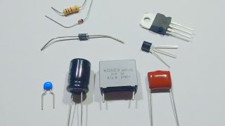
this circuit requires ONLY a transistor, a string of LED's in series, and your caps and relay.
i plan on modifying this greatly, this is just a BASIC setup to give you an idea of how it works..
i noticed that a simple small gen coil charging a cap is more than enough to fire the relay, which i will put in place of the 9v. i have not totally thought over the component requirements as much more voltage and current may require some type of FWBR to keep spikes from damaging the LEDs. so far this basic circuit has been pulsing for hours now just the way it is in its demonstration form.
my ultimate plan is to use this circuit to pulse gen coil caps back to my run battery, that i charge using the reed switch pulse method that i have found to generate HV spikes. this way i can turn that into usable current being that i can charge caps to over 100v that way from induction coils.
ok more explanation..
the timing cap and led string is in parallel.
the NPN transistor has its base and emitter "tapped" in between the LED string (just so the base wont initially see the cap's voltage). another capacitor is in series with the C and E on the NPN also in series with the relay. this capacitor can be kept charged any way you want.
when the timing capacitor has reached enough potential voltage (around 25v in this case), it will energize the LED string all the way through, and begin to send a tiny bit of real current across the Base of the NPN. this instantly causes the NPN to switch on allowing the relay cap to discharge and switch the relay, while simultaneously discharging the timing cap so it has to refill again and continue the cycle.
the relay is what switches the main cap bank holding the most charge, but the timing cap is also dumped into the output as well. the only energy that is lost is what is put into the relay cap since that is used for the relay coil. a 555 timer will lose the same energy but more.
the LED's are not losing hardly any energy because real current only passes through them in an instant pulse. the light is coming from voltage potential alone.
i used this effectively on a motor im still making tweaks so ill make a vid of it working on a motor when its done