Published On Jun 6, 2024
code
void setup() {
Serial.begin(9600);
}
void loop() {
int sensorValue = analogRead(A0);
Serial.println(sensorValue);
delay(500);
}
analog and digital outputs in the context of a serial monitor, let's break down the concepts and how they are typically used in microcontroller programming, such as with an Arduino.
Analog Output
Analog output typically involves generating a varying voltage or current signal, which is often used to control devices like LEDs, motors, or other analog devices. In microcontrollers like the Arduino, analog output is achieved using Pulse Width Modulation (PWM). PWM allows the simulation of an analog signal by rapidly switching the digital pin between high and low states with a certain duty cycle.
Digital Output
Digital output involves setting a pin to either a HIGH or LOW state, corresponding to the maximum voltage (e.g., 5V) or ground (0V) respectively. This is useful for turning on/off LEDs, relays, or other digital devices.
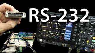
Using Serial Monitor
The serial monitor in Arduino IDE (or any similar environment) is a tool that allows you to see the output of your microcontroller in real-time. By using the Serial.begin() function in setup() to initialize communication and Serial.print() or Serial.println() to send data to the monitor, you can easily debug and understand what your code is doing.