Published On Jul 12, 2020
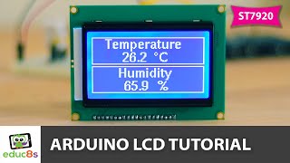
hi, in this video, we are going to connect 16x2 lcd with our arduino uno. this lcd comes in our arduino starter kit and along with this lcd we also get an I2C module in the kit to run the LCD. but in today's video we are going to directly connect the lcd with arduino.
There are total 16 pins in the lcd.
1. pin 1 of lcd connects with the GND of arduino
2. pin 2 connects with 5V
3. pin 3 (Vo) connects with potentiometer or PWM pin of arduino
4. pin 4 (Register Select ) connects with any of the digital pin of Arduino ( for example, pin 12 )
5. pin 5 ( RW ) is the read and write pin, which connects with GND
6. pin 6 (E) is data enable pin which connects with pin 11
7. We will not connect D0, D1,D2,D3
8. pin D7 with pin 2 ( of arduino ), D6 with pin 3 ( of arduino ), D5 with pin 4 ( of arduino ), D4 with pin 5 ( of arduino ).
9. pin 15 and 16 are for the led light of lcd. pin 15 connects with 5V and 16 connects with GND.
Vo :
Vo pin is the contrast pin of lcd. by giving it different values, we can adjust contrast of lcd. So, we can connect it directly with the GND of arduino but contrast will be maximum so we have other two options. First we can connect it with any of the PWM pin of arduino and in the sketch (code ) we can call analogWrite() function and adjust the contrast as shown in the video. Secondly, we can connect Vo with the potentiometer to change the contrast as shown in video .
REGISTER SELECT (RS):
there are two modes, one is command mode and other is data mode. RS pin selects either of the two modes. if we want to select the command mode then we connect RS pin with GND and if we want to select the data mode then we connect RS pin with 5V.
link for code:
https://drive.google.com/file/d/1ewJk...
facebook page:
https://web.facebook.com/Global-Spy-H...